
Insulation displacement connectors (IDC) terminate insulated conductors by pressing them into slotted contacts that displace the insulation and make electrical contact with the conductor. This approach can terminate many conductors at once and is widely used with ribbon cable, board connectors, D-sub, Centronics and internal equipment harnesses.
TE Connectivity describes IDC systems as allowing wire termination without stripping or crimping, reducing assembly steps when the connector, conductor size and tooling are correctly matched.
Select IDC components by connector family, contact count, conductor spacing, wire size, cable orientation and strain-relief requirements. The contact geometry must match the insulation and conductor dimensions for a reliable termination.


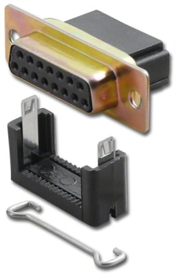


Match the ribbon cable pitch to the connector. Many traditional IDC ribbon assemblies use 0.050-inch conductor spacing, but other systems exist and require different contact geometry.
Confirm position count and keying. Polarizing keys, strain-relief covers and connector orientation help prevent reversed or offset mating in service.
Use the proper IDC press or hand tool so the connector seats evenly across all conductors. Uneven pressure can produce partially seated contacts or damage the connector body.
IDC refers to the termination method, not the external interface. IDC termination can appear behind D-sub, Centronics, card-edge, PCB header and other connector formats, so select both the cable termination and mating interface correctly.
