
3.5mm audio jacks are compact female receptacles used on headphones, computers, communication devices, control panels and embedded electronics. Correct selection requires matching the contact count, mounting style, switching contacts, board footprint and wiring convention—not just the nominal 3.5mm diameter.
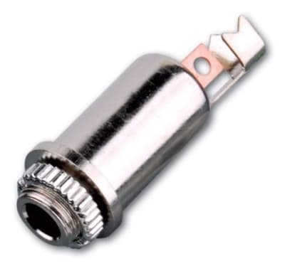



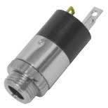
3.5mm jacks may mount directly to a printed-circuit board, attach to a chassis with a threaded bushing, integrate into a molded cable, or serve as inline extension receptacles. PCB versions vary widely in footprint and orientation, so a visually similar part may not fit an existing board. Panel versions must match hole diameter, bushing length and rear clearance.
TS, TRS and TRRS jacks are designed around different numbers of conductive contacts. A jack may accept a plug mechanically while failing electrically if contact positions do not line up with the intended circuit. Headset and microphone applications are particularly sensitive to pin assignment, so the equipment schematic or original connector should be used as the reference.
Many 3.5mm receptacles include normally closed or detect contacts that change state when a plug is inserted. These can disconnect an internal speaker, route audio, signal a controller or detect accessory presence. A replacement jack without the required switched contacts may pass audio but still leave the device malfunctioning.
Portable and frequently serviced equipment places significant mechanical stress on small jacks. PCB-mounted styles depend on solder joints and board anchors for support, while panel-mounted styles transfer force to the chassis. In high-cycle environments, consider retention force, mounting tabs and how cable leverage will act on the connector.
Crackling, channel loss or audio that returns when pressure is applied to the plug may indicate oxidized contacts, a worn spring contact or cracked solder joints. A missing internal-speaker function may point to a failed switched contact. Before replacing the jack, inspect board soldering and verify the plug itself is correctly wired.
In addition to TS/TRS/TRRS contact count, identify whether the receptacle includes plug-detect, speaker-disconnect or other switching contacts. On compact electronics these auxiliary contacts often account for more terminal pins than the audio circuit itself. For board replacement, measure body height and connector setback from the PCB edge because the front opening must align with the enclosure.
Use this category for female 3.5mm receptacles mounted to equipment, boards or cables. Male cable-end parts belong under 3.5mm Audio Plugs & Connectors. Size-conversion adapters belong in Audio Plug & Jack Adapters. Keeping these functions separate makes it easier to diagnose whether a fault is in the cable, the equipment jack or simply a connector-size mismatch.
Small audio jacks often perform more than one job. A receptacle may route audio, disconnect an internal loudspeaker and signal insertion to a controller at the same time. If a device behaves incorrectly after a jack replacement even though sound passes, recheck the switched or detect contacts and compare them with the original schematic or connector.
It includes extra contacts that open or close when a plug is inserted, often to disconnect a speaker or provide plug-detect functionality.
Not automatically. Contact positions, switching functions, footprint and circuit wiring all need to match.
Body shape, pin spacing, switch contacts and mounting anchors vary widely even when the front opening looks identical.
Wallco can help narrow connector family, gender, contact count, termination, cable fit and application requirements. For replacements, provide the equipment manufacturer/model, clear photos of the mating face and side profile, and any dimensions or pinout information available.
