
RCA jacks and receptacles are female connectors used on equipment panels, wall plates, patch assemblies and circuit boards for analog audio, video and other low-level signals. Selection depends on mounting style, insulation from the panel, contact layout, spacing, signal use and how the rear termination connects to the equipment wiring.
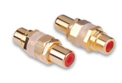
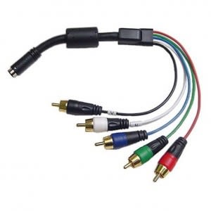

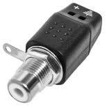

RCA jacks are available for chassis mounting, printed-circuit boards, wall plates and inline cable couplers. Panel-mount versions may use a threaded bushing and nut, while PCB jacks rely on board footprint and mechanical support. Inline receptacles are useful when extending or adapting cable assemblies. The mounting style must match both the mechanical opening and the electrical grounding scheme of the equipment.
Some chassis jacks intentionally bond the outer RCA contact to a conductive panel; others use insulating washers or plastic bodies to keep signal ground isolated from chassis ground. That distinction matters in audio systems where grounding topology can influence hum and ground-loop behavior. When replacing a jack, preserve the original isolation method unless the circuit design is being intentionally changed.
Single, dual and multi-position RCA jack assemblies are common. Stereo audio often uses red and white channel identification, while composite video is frequently yellow and component video commonly uses green, blue and red. In service work, color helps with human identification but the wiring and equipment labels determine the actual signal. Multi-jack blocks should be checked for spacing, board pinout and shared-ground construction.
A good receptacle must hold the plug firmly without excessive insertion force. Worn spring contacts can cause intermittent channels or noise when the cable is moved. Panel jacks also need enough thread engagement and anti-rotation support to survive repeated use. In high-service environments such as test benches, studios and training rooms, mechanical robustness can be more important than cosmetic style.
Measure panel-hole diameter, bushing length, center spacing and rear clearance. For PCB types, match pin location and body footprint; similar-looking jacks are often not drop-in substitutes. Confirm whether the jack is isolated from the panel, whether the outer contact is commoned with neighboring positions and what rear termination is required—solder lug, quick-connect, PCB pin or cable tail.
For panel work, verify the insulating shoulder washers and nut arrangement as carefully as the electrical contacts. A jack installed in a conductive panel can change the grounding scheme if its outer contact unintentionally touches chassis metal. For multi-position assemblies, check center-to-center spacing and whether the outer contacts are independent or tied together internally, especially in stereo or multi-channel equipment.
Use a receptacle when the connection must be fixed to equipment, a wall plate or a panel. Cable-end male terminations belong under RCA Plugs, while inline gender changes and connector transitions belong under RCA Adapters & Couplers. This distinction is particularly useful when repairing older electronics because a worn chassis jack and a damaged cable plug create similar symptoms but require different parts.
A frequent replacement error is overlooking the jack's grounding and mounting details. Installing a conductive bushing where the original jack was insulated can introduce noise, while using a PCB jack with a slightly different pin layout can damage traces or place stress on the board. Match the electrical role and the mechanical footprint before treating two visually similar receptacles as equivalent.
Yes. Depending on the design, it may intentionally ground to the panel or use insulating hardware to remain electrically isolated.
A worn receptacle, cracked solder joint or poor cable termination can all cause intermittent contact. Inspect the jack as well as the plug.
No. Dual assemblies are often used for stereo audio, but they can also carry two independent signals. Follow the circuit or equipment labeling.
Wallco can help narrow connector family, gender, contact count, termination, cable fit and application requirements. For replacements, provide the equipment manufacturer/model, clear photos of the mating face and side profile, and any dimensions or pinout information available.
