
Coaxial cable assemblies maintain a controlled relationship between center conductor, dielectric and shield, which allows RF and high-frequency video signals to travel with predictable impedance and shielding. Factory-installed connectors help preserve that geometry at the termination point.
The most important selection factor is impedance. Many RF and instrumentation systems use 50-ohm assemblies, while video, broadcast and cable-TV applications commonly use 75-ohm coax. Connector family, cable type, frequency, attenuation, shielding, length and flexibility must also fit the application.
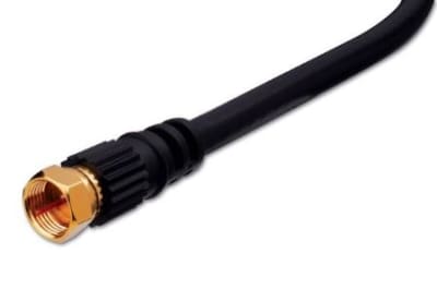

Fifty-ohm coax is widely used for RF transmit/receive, antennas, wireless infrastructure and test equipment. Seventy-five-ohm coax is common for video, broadcast and broadband distribution. Mixing impedance can create reflections and loss, especially as frequency rises, even when the connectors appear to mate.
BNC connectors are common in broadcast, test and instrumentation environments, while F-type connectors dominate many broadband and television installations. Other coaxial connector families serve RF and microwave applications. Verify connector gender, impedance and frequency rating, not just mechanical size.
Coaxial loss increases with both frequency and length. A cable that performs well for low-frequency video may have excessive loss for a higher-frequency RF link. Larger-diameter coax often provides lower attenuation but is less flexible, so routing and minimum bend radius must be considered along with electrical performance.
Braided, foil and multi-layer shields provide different levels of shielding effectiveness and flexibility. Outdoor assemblies may require UV resistance, moisture sealing or weatherproof connector interfaces. Portable test leads may prioritize flexibility and repeated connection cycles instead.
Identify system impedance, frequency or video standard, connector at each end and required length. Then check attenuation, shielding, flexibility and environmental exposure. For precision or high-frequency systems, use manufacturer performance data rather than assuming all cables with the same connector are equivalent.
Factory assemblies are useful where connector installation quality must be repeatable, while bulk coax is appropriate for long permanent pathways or custom field lengths. At RF and digital-video frequencies, connector installation affects the transmission line, so field termination should use connector models, preparation dimensions and tooling specified for the exact cable type.
Before ordering coaxial cable assemblies, record the equipment interfaces at both ends, the required electrical or signal standard, cable length, installation environment and any existing part number or cable marking. For replacements, matching only the connector can be misleading; confirm the underlying signal type, impedance, conductor configuration, performance rating and environmental requirements. Providing those details helps Wallco narrow the correct product and avoid compatibility problems.
Cable performance is a system issue: the source, destination, connectors, cable construction, length and installation conditions all contribute to the result. A cable that physically fits is not automatically electrically compatible, and a higher advertised category or bandwidth does not correct a mismatched interface. When in doubt, start with the equipment manufacturer specifications and choose a cable assembly or bulk cable that explicitly supports those requirements.
Wallco can help compare cable construction, connectors, ratings and application requirements when you are selecting a new installation product or replacing an existing cable. If available, provide the connected equipment models, existing cable markings, required length and installation environment so the options can be narrowed accurately.