
PCB headers and socket strips form modular board-level interconnects used in controls, embedded electronics, test fixtures, prototyping and OEM equipment. A pin header provides exposed male contacts while a mating socket strip provides female contacts, allowing boards, harnesses or modules to be connected and separated without hardwiring every circuit.
The most important mechanical variables are pitch, number of positions or rows, pin length, mating depth and orientation. Straight and right-angle versions support different PCB layouts, while breakaway strips allow some families to be cut to the required position count.
Electrical suitability depends on contact design, plating, current, voltage and the environment. Do not select a header only by pin count when the mating interface, spacing or contact rating differs.

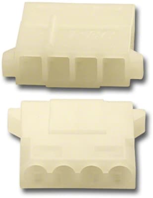
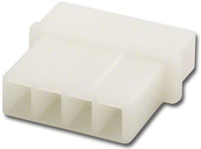


Match the pitch first. Common board-level systems use 2.54 mm (0.100 inch) spacing, but many smaller and larger pitches exist and are not mechanically interchangeable.
Confirm rows and positions, then check straight versus right-angle orientation and whether the pins must extend through the board, above the board or on both sides for stacking.
If a socket strip must mate with an existing header, verify pin cross-section, mating length and contact acceptance range in addition to pitch.
For power or higher-current circuits, use the manufacturer current and temperature ratings rather than assuming all pin headers are equivalent. For high-speed signaling, also consider connector geometry and signal-integrity requirements.
