
Female BNC interfaces used on panels, equipment, adapters and cable assemblies where a mating BNC plug must lock securely by bayonet coupling. Selection centers on impedance, mounting style, termination, cable or board interface, frequency rating and panel geometry.
Wallco organizes bnc jacks & female connectors within BNC Connectors & Adapters so engineers, technicians, installers, OEM buyers and maintenance teams can narrow the correct RF component by the electrical, mechanical and installation details that determine real compatibility.


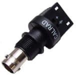


Female BNC interfaces used on panels, equipment, adapters and cable assemblies where a mating BNC plug must lock securely by bayonet coupling. The correct part must match the complete transmission-line and mechanical interface, not merely the connector-family name.
Common applications include broadcast equipment, oscilloscopes, signal generators, cameras, communications and industrial systems. For replacement work, document both mating halves, the coax or board interface, mounting method and system impedance before selecting a substitute.
BNC uses a bayonet coupling that allows quick connection and disconnection while providing positive mechanical retention. The family is produced in both 50-ohm and 75-ohm versions. Those versions can look similar, so impedance must be treated as an electrical requirement, not inferred from appearance. Standard BNC products are used broadly in RF, instrumentation and video; higher-performance broadcast designs can extend into multi-gigahertz SDI applications when paired with compatible cable.
For a cable-mounted BNC, identify the exact coax before selecting the connector. Center conductor diameter, dielectric diameter, braid/jacket dimensions and cable flexibility drive fit. Crimp connectors require the correct stripping dimensions and die set; clamp or solder styles have their own assembly procedure. A mechanically successful termination can still perform poorly at RF if dimensions, shield continuity or center-contact installation are wrong.
The usable frequency of the system is limited by the complete signal path: connector design, cable, adapters, assembly quality and load. For higher-frequency RF and digital video, review manufacturer return-loss or VSWR data and do not assume a generic connector is suitable simply because it mates. Keep unnecessary adapters and discontinuities to a minimum when signal integrity is important.
BNC jacks may terminate to coax, mount through a panel, solder to a PCB or form part of an adapter. Panel jacks can use single-hole bulkhead hardware, flange mounting or isolated designs. For replacements, measure panel cutout, available rear depth and whether the connector body must bond electrically to the chassis.
A cable jack requires the same cable-group checks as a plug. PCB jacks add footprint, launch geometry and board thickness. Solder-terminal versions require enough room to route coax without forcing sharp bends near the connector. These mounting details are often more important than nominal BNC compatibility.
When replacing an existing RF connector, the safest cross-reference starts with the original manufacturer part number or a complete set of dimensions and electrical requirements. Similar-looking RF connectors can differ in impedance, contact geometry, cable fit, mounting threads, plating and frequency performance. If the original part number is unavailable, identify the mating connector, cable manufacturer and cable number, panel/board arrangement and application frequency before selecting an alternate.
For cable assemblies, consider whether replacing the complete assembly is more reliable than reterminating a damaged connector in the field. High-frequency performance depends heavily on assembly workmanship, and a factory-terminated cable can reduce uncertainty when tooling or inspection capability is limited.
What is the most important specification when choosing bnc jacks & female connectors? Start with the exact mating interface and system impedance, then verify cable or mounting compatibility, termination method and frequency. No single specification is enough by itself.
Can two RF connectors mate physically and still be the wrong combination? Yes. Impedance, reverse-polarity center contacts, cable fit and electrical performance can differ even where mechanical mating seems possible. Always verify the complete specification.
Does a connector family name guarantee a frequency or environmental rating? No. Ratings vary by individual design, cable and assembly. Use the manufacturer datasheet when frequency, sealing, power or return loss is critical.
If you are replacing an existing bnc jacks & female connectors or specifying a connector for a new RF, video or communications application, provide Wallco with the equipment interface, cable type, impedance, required frequency, mounting style and any environmental requirements. Those details make it much easier to narrow the correct connector and avoid an electrically or mechanically incompatible substitution.
